
← Back to projects
Biomass fuel preparation · Shanxi, China
Biomass fuel preparation for an existing coal-powder hot-water-boiler plant
The project design adds a dedicated biomass drying, milling, storage and feeding route alongside an existing coal-powder fuel system. The design arranges two parallel rotary dryers, an eight-mill indoor preparation group and enclosed conveying between preparation, storage and the boiler-side feeding interfaces.
Shandong Junminghe Engineering Design Co., Ltd. led the system and equipment-layout design for the biomass fuel-preparation facilities.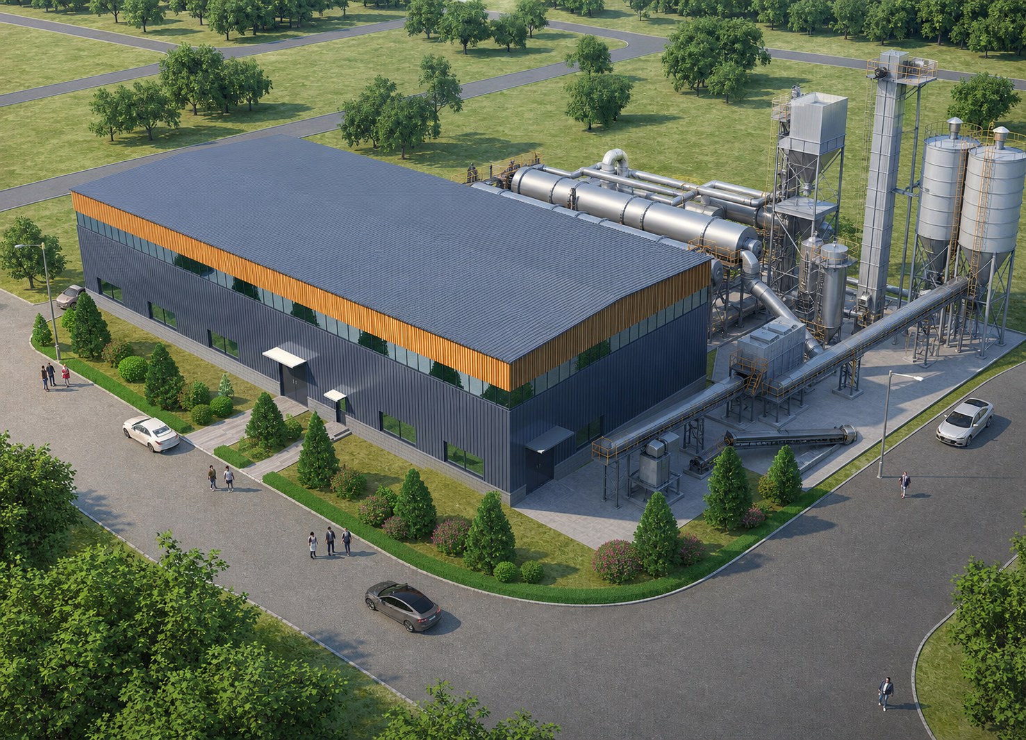
Project need
Add a biomass route without obscuring the existing fuel system
The existing plant was designed around coal-powder hot-water boilers. The retrofit therefore treats biomass preparation as a complete parallel process rather than an isolated mill or feeder addition. Raw material must be received, dried, buffered, milled, separated, stored and metered before it reaches the boiler-side fuel interface.
This creates a multi-discipline coordination task across material handling, hot flue-gas drying, dust collection, pneumatic conveying, workshop arrangement, outdoor structures and the retained boiler and environmental-treatment boundaries.
Engineering scope
System design carried through the equipment arrangement
Shandong Junminghe developed the fuel-preparation process and the mechanical arrangement connecting outdoor drying, indoor milling, gas-solid separation, powder storage and boiler-side feeding.
Process definition
Coordinate receiving, drying, buffering, fine milling, filtration, pneumatic transfer, storage and controlled feeding as one material path.
Equipment arrangement
Resolve the two long outdoor dryers, elevated conveying and eight-mill indoor group against the building, structure and maintenance zones.
Air and gas interfaces
Connect the flue-gas heat source, dryer exhaust, fans, separation and filtration with the retained environmental-treatment boundary.
Plant integration
Define the new biomass preparation and feeding interfaces while keeping the existing coal-powder route identifiable.
Fuel-preparation path
From incoming biomass to a defined boiler-side interface
- 01
Receive and protect the line
Feed hoppers, enclosed conveyors, iron removal and spark-control equipment establish the incoming-material route before drying.
- 02
Dry with recovered process heat
Two rotary drum dryers use high-temperature boiler flue gas as the design heat source. The design basis uses approximately 300°C at the dryer inlet and 140°C at the outlet, with post-drying gas directed to the plant environmental-treatment system.
- 03
Buffer and mill
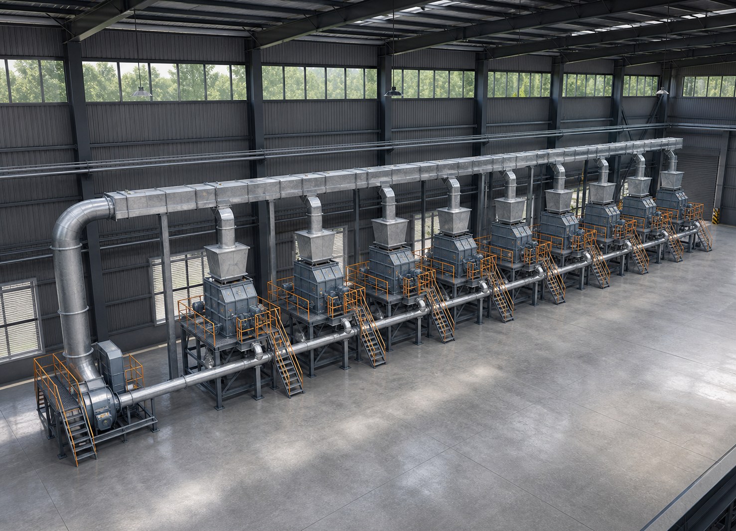
Dried material is lifted and buffered before entering eight parallel impact mills arranged as one indoor preparation group.
- 04
Separate, store and feed
Gas-solid separation, bag filtration and pneumatic conveying transfer the prepared powder to two storage silos before controlled boiler-side feeding.
Indoor equipment arrangement
Eight impact mills organised as one operating line
The interior layout places eight mills in a single row beneath the common feeding and collection arrangement. A continuous service aisle, local lifting access, dust-control connections and the overhead process route are treated as part of the equipment system rather than leftover building space.
Integration decisions
The equipment chain is only as strong as its interfaces
Keep the fuel routes identifiable
The biomass line is arranged alongside the retained coal-powder system, keeping the new preparation, storage and feeding boundaries explicit.
Use the available flue-gas heat
Duct pressure, temperature, insulation, filtration and fan duty are coordinated around the boiler flue-gas drying source and the environmental-treatment return path.
Coordinate long outdoor equipment
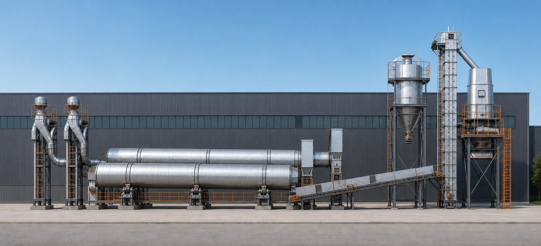
Two 24 m dryers, inclined conveyors, the bucket elevator, buffer bin and silos are arranged together with structure, access, duct routing and maintenance space.
Design the whole powder path
Fine milling connects directly to separation, filtration, pneumatic transfer, storage and controlled discharge instead of being selected as an isolated machine group.
Outdoor process arrangement
Two parallel dryers, one coordinated elevation
The side elevation keeps the two rotary dryers at the same operating level, then follows the material path through the inclined conveyor, bucket elevator and elevated bin system. The near-orthographic view keeps the principal equipment relationships easy to read.
Practical value
A defined route from raw biomass to boiler-ready fuel handling
- 01Complete process boundary
Coordinate receiving, drying, milling, filtration, storage and feeding as one fuel-preparation package.
- 02Retained-plant integration
Define the biomass route around the existing boiler-fuel and environmental-treatment interfaces.
- 03Layout-led coordination
Resolve outdoor dryers, elevated conveying and the indoor milling group against building, structure and access constraints.
- 04Procurement-ready interfaces
Align equipment duty, material flow, air path, connection points and package boundaries before supplier coordination.
Start with the fuel and plant data
Planning a biomass co-firing fuel-preparation system?
Share the boiler type and duty, biomass source and particle size, incoming and target moisture, required treatment capacity, target co-firing strategy, available flue-gas conditions, site boundary, storage requirement and environmental-treatment interfaces. We can help define the process route, equipment interfaces and engineering package around the actual requirement.